When I was a kid, I used to go for swimming lessons in the local leisure centre. In the lobby there were three machines: one that vended miscellaneous swimming items (cheap goggles, earplugs, etc), one that sold various less-than-healthy snacks, and one arcade game machine playing a game called The NewZealand Story.
I never played it (pocket money was precious), but I must have spent ages watching the game play itself in demo mode. If you’ve never come across it, The NewZealand Story is an odd, cute platform/maze game in which you, as a small, yellow, fluffy “kiwi”, set out to rescue all the other kiwis from a kidnapping walrus. It’s very cute, and very hard.
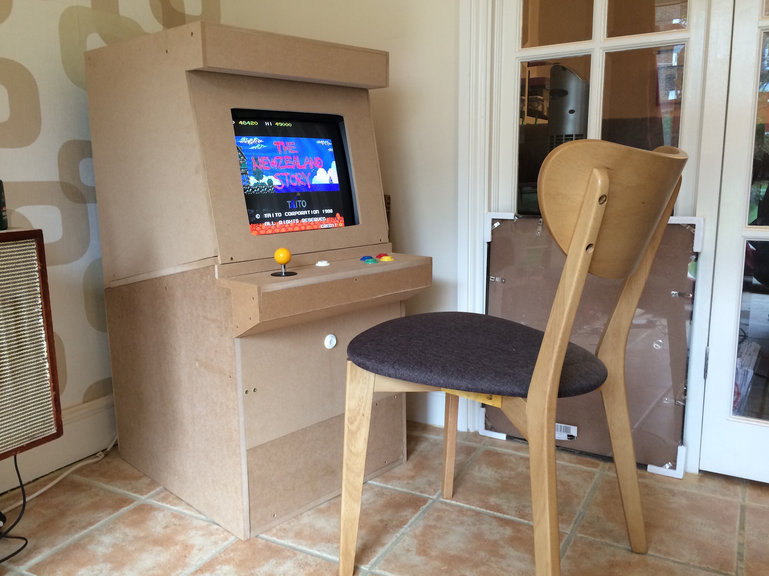
Jump forward 27 years or so, and while digging through eBay I spotted something unusual: a PCB for the game, tested and working, for not too much money. Nobody else put a bid on it, and I was soon the proud owner of the game. My plan was to build it into a proper, freestanding arcade machine – but about half the proper size, as we don’t have that much spare room. And here it is, in all its MDF-y glory:

And below, for anyone considering a similar project, is what I learned along the way.
JAM-er-What?
My copy of TNZS, like most other games from the late 1980s and 1990s, is what’s called a JAMMA PCB. This means that it has a standard connector that provides power, sound and video outputs, and inputs for all the controls. You can see the long, gold connector – it’s double-sided – on the left in the photo below. If the game you want to make is JAMMA, you should be able to use lots of standard parts, including a “harness” of all the required cables (but see below for a note on power). If you’re working with a non-JAMMA game, you’ll be in for much more soldering.

Bootleg Boards are Cranky
When I bought my TNZS PCB (above), I didn’t know it was a bootleg. On unwrapping it, though, I noticed that there were no Taito labels or markings, which seemed odd. More unusually still, on hooking it up for the first time I found that the picture on the display was upside down, with the dipswitches that control inversion seemingly ignored. A bit of googling later and I learned that upside-down video output is a “feature” common to bootleg copies of TNZS – nothing to do but flip the display itself upside down to match. So far, so odd.

CRT vs LCD
And speaking of displays: my plan had been to use an old 17in LCD screen that I had going spare. It had DVI and VGA inputs, so I bought a Gonbes GBS-8220 converter (manual link here). This converts all manner of video formats, including arcade-style R-G-B-CSync to VGA, and worked really well with a more modern JAMMA board I tested it on. With the TNZS board, though, it failed completely – the video would roll vertically, no matter what settings were used. I suspect, but can’t confirm, that it struggles with PAL 50Hz video via R-G-B-CS.

In the end, the only solution to this was to use an old-fashioned CRT screen instead. I picked up the 17in JVC broadcast monitor display pictured above, complete with R-G-B-CS input card, from eBay, and the result looks fantastic: no rolling, and bright, vivid colours with scanlines, just like a proper 1980s arcade machine. The only downsides are weight (the display alone is 20kg) and that I had to create a custom video connector to feed its four BNC inputs, but that proved simple enough – a four phono connector panel, with the grounds all shared, works great.

Voltage Drops in JAMMA Wiring
My PCB may not have had any Taito markings, but it did have a label – in German – noting that it required exactly 5v to run, no more and no less. Arcade power supplies have a voltage trim, so this should be easy, but I noticed that with the PSU putting out exactly 5v, the voltage at the PCB edge was about 4.7v, with the voltage across an IC on the board slightly lower still. Solution, courtesy of the internet: I removed the 5v and ground wires from the JAMMA wiring, and replaced those (puny) cables with some mains-quality cable. This fixed it immediately – 5v at the PCB became 5v at the edge. If I were to build another JAMMA project, I’d do this before anything else.
Arcade PSUs are Scary
On a related note: rather than adapt an old ATX computer power supply, I bought a proper arcade one. I’d never seen one before, so was slightly surprised to see that the 240v input isn’t a socket, but rather exposed screw terminals. This is fine, as long as you’re happy to work around mains voltage with the appropriate precautions, but if you’re not then a PC PSU might be a better bet.
Snap, Crackle and Pop
The biggest problem I had was sound. The JAMMA system should make audio easy: it’s all done on the PCB, which has edge connectors that go straight to a speaker or speakers (8ohm total impedence). However, my PCB sounded awful. As soon as it powered up, a loud BUZZZZSSSSSTTTTMMMZZZZ noise would erupt from the speaker, and continue through the game. No good at all.

In the end, after a whole lot of testing, I found that the noise appeared in the power amplifier section of the board, and that clean audio could be lifted off before that stage. I desoldered the volume pot, soldered in some pins, and fitted the cabinet with a cheap (£7) mono amplifier that can run from the 12v line of the PSU, as shown above. It’s clumsy, and means that the cabinet is no longer fully JAMMA, but works well – I also fitted a new volume control, as it’s surprisingly powerful.
Coins and Controls
My JAMMA cabling had two lines for a coin mech: one with a 3 pin socket on the end and a 12v power line, which I stole to power the audio amplifier, and one simple cable. Most coin mechanisms seem to require 12v power; I decided not to bother with one and simply rigged up a button to add credits. Lazy, simple, works.

And speaking of buttons: you can pay a lot of money for quality arcade controls, but I didn’t. I used a cheap, own-brand joystick and buttons from Arcade World, and although serious arcade fans might notice the difference they feel great to me – positive and clicky and just what I’d expected. Mounting the buttons into the control panel for the first time, above, is one of those jobs that’s insanely satisfying.